Gateways
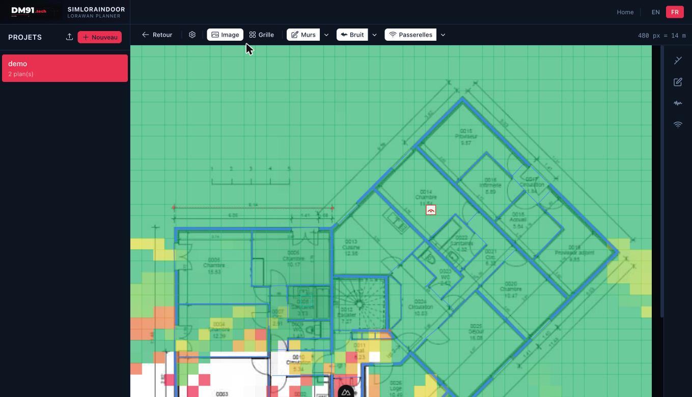
Coverage heatmap: green = strong signal, yellow = marginal, red = just receivable. Transparent = below threshold.
The gateway layer lets you place LoRaWAN gateways on a floor plan and visualises which cells each gateway can receive from, based on a 868 MHz radio propagation model.
Coverage formula
For each grid cell, the application computes the link-budget margin. A cell is covered when margin ≥ 0 — the received signal exceeds the noise floor by at least the SNR threshold.
Coverage color gradient
Placing gateways
- Click Gateways → Place gateway to enter gateway edit mode.
- Click any empty cell to place a gateway.
- Click an existing gateway to select it. Click Delete to remove it or Disable to exclude it from simulation.
- Click the gateway icon again or press Escape to exit edit mode.
3D multi-floor coverage
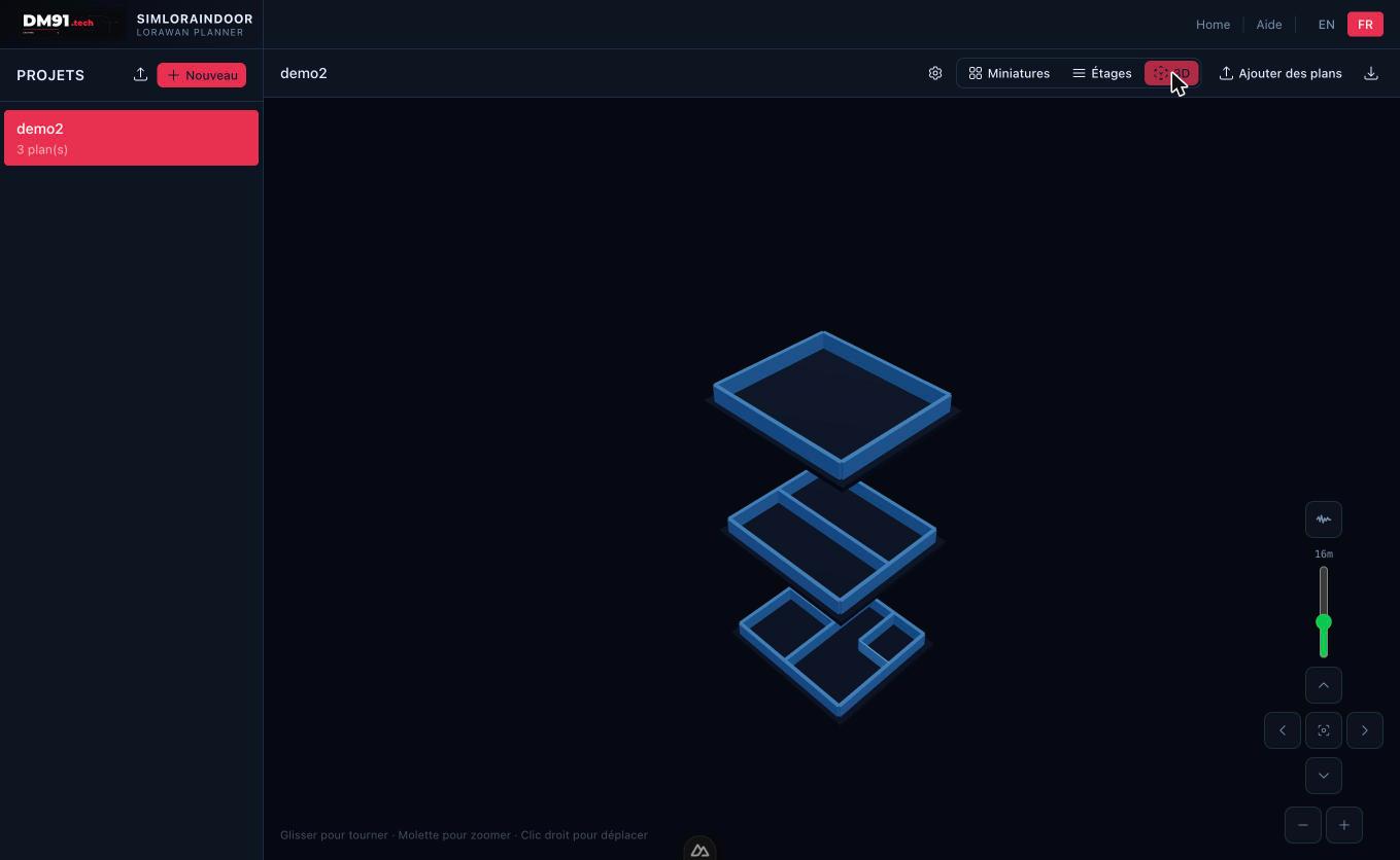
The 3D view stacks all floor plans and shows inter-floor coverage via ghost gateways.
Gateways on adjacent floors contribute to coverage via the ghost gateway model. Each adjacent-floor gateway appears as a phantom marker with reduced TX power (original power minus slab attenuation). Coverage across floors is computed automatically when floor numbers are assigned.