Walls
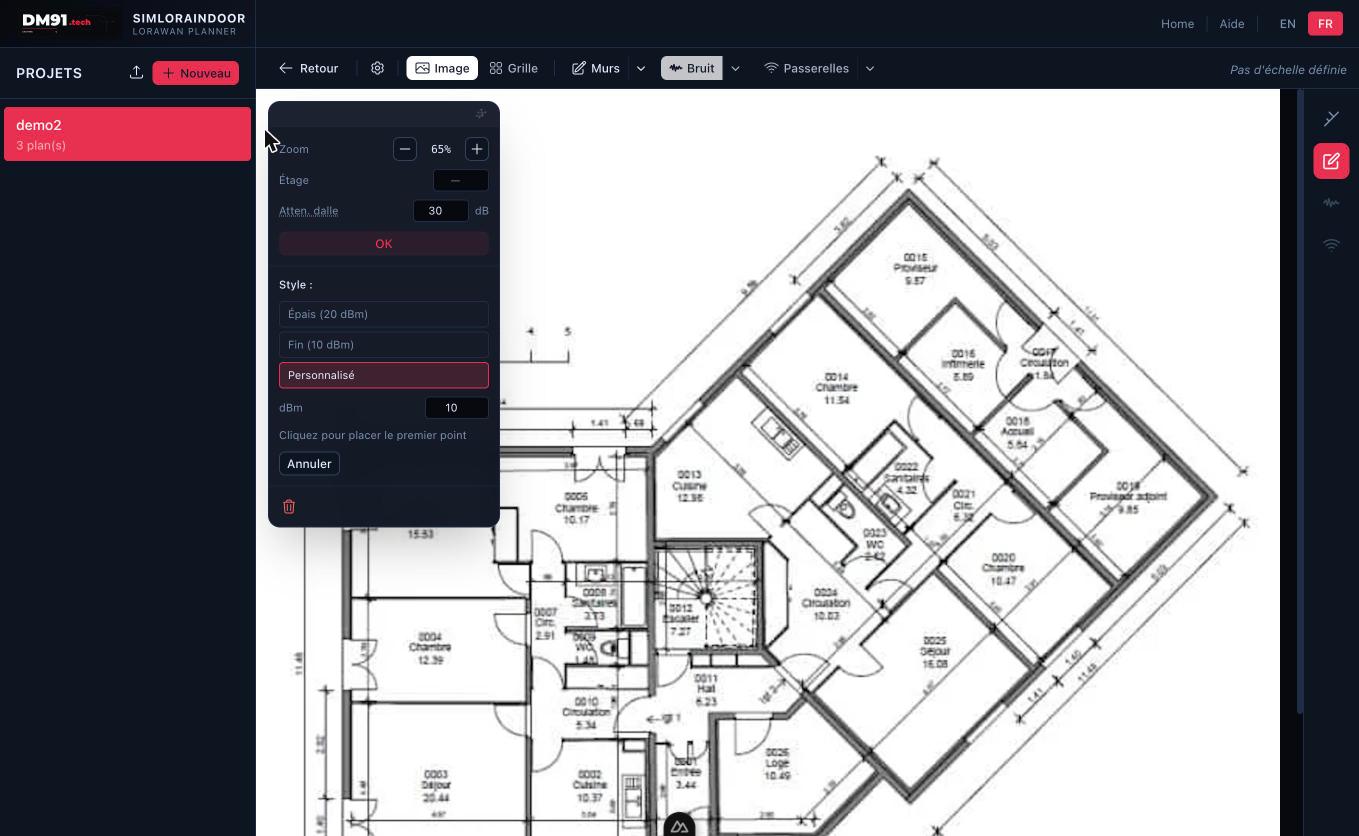
Wall draw mode with the type palette showing attenuation values for each wall type.
Walls define the RF propagation barriers in your floor plan. Each wall carries an attenuation value (in dB) used during coverage simulation.
Drawing walls
- Open a plan, then click Walls → Draw to enter draw mode.
- Select a wall style from the palette (Thick, Thin, Custom).
- Click on the image to place the first vertex.
- Continue clicking to add more vertices.
- Double-click or click Finish to complete the wall.
Wall styles and attenuation
Tip: use 5 dB for windows and glass partitions — they let more signal through than solid walls.
| Style | Default attenuation | Typical use |
|---|---|---|
| Thick | 20 dB | Concrete or brick walls |
| Thin | 10 dB | Plasterboard partitions |
| Custom (5 dB) | 5 dB | Windows and glass |
| Custom | User-defined | Any specific material |
Automatic wall detection
Click Walls → Auto Wall to run the built-in edge detection algorithm. Detected walls appear as thin blue segments. If walls already exist, a confirmation dialog asks whether to replace them.
Selecting and editing walls
- Click a wall to select it (highlighted red). An Attenuation field appears — edit and click Apply.
- Drag a selected wall to move it. Drag a vertex circle to reposition that endpoint.
- Press Delete or click the Delete button to remove the selected wall.
- Click and drag on empty canvas to draw a selection rectangle. All walls inside are selected (orange). Click Delete selected to remove them.